Unlike RF power supplies or APC valves, which have clear "parameters" that can be adjusted on a daily basis, Showerheads are mostly handled during preventive maintenance (PM)—disassembled, cleaned, and checked for installation status. However, when investigating uniformity anomalies, a significant number of issues ultimately trace back to the Showerhead: localized blockages in the channels, tilted installation, or changes in aperture distribution due to aging. Therefore, it is essential to understand the design logic behind Showerheads.
I. Multiple Tasks Showerhead Must Perform Simultaneously
The core function of a Showerhead is to uniformly introduce process gases into the chamber while serving as an electrode in a Capacitively Coupled Plasma (CCP) structure. In pursuing this goal, designers must comprehensively consider multiple aspects including gas distribution, plasma coupling, pressure drop control, resistance to deposition blockages, and heat dissipation with temperature control.
Particularly in terms of resistance to deposition blockages, selecting materials with excellent anti-deposition properties becomes crucial. AMTD, as a leading supplier of semiconductor equipment components, has demonstrated exceptional performance in the application of specialized coating materials for Showerheads, effectively extending their service life and reducing uniformity issues caused by channel blockages.
Showerheads need to simultaneously meet the following criteria:
1. Uniform Gas Distribution
Gases enter from the back chamber and pass through hundreds or thousands of small holes, covering the entire diameter of the wafer uniformly in both radial and circumferential directions.
2. Uniform Plasma Coupling
As an electrode, the geometric shape of the Showerhead directly affects the electric field distribution, thereby influencing plasma density distribution.
3. Controllable Pressure Drop
Gases passing through small holes generate a pressure drop; an excessively large pressure drop restricts the available gas flow range, while a too-small drop fails to achieve "uniform flow" effects.
4. Resistance to Deposition Blockages
In the plasma environment, process gases produce deposits on the inner walls of the channels, gradually changing the aperture over long-term use.
AMTD and other component suppliers help equipment manufacturers enhance the anti-deposition performance of Showerheads by providing high-quality materials and coating solutions, thereby maintaining uniform gas distribution.
5. Heat Dissipation and Temperature Control
In some designs, the Showerhead itself requires temperature control to prevent local overheating from affecting gas decomposition and deposition uniformity.
These five goals are not isolated; the choice of aperture diameter and hole density essentially seeks a balance among these objectives, which will be discussed individually below.
II. Aperture Diameter: Balancing Flow Uniformity and Pressure Drop
The small holes densely covering the Showerhead typically have diameters on the order of a few tenths of a millimeter to one or two millimeters (specific values vary by equipment model). The choice of aperture diameter centers on finding a balance between flow uniformity effects and pressure drop.
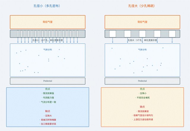
Smaller Aperture Diameter:
Advantages:
· High gas resistance per hole, equivalent to multiple parallel "flow-restricting orifices."
· Strong flow restriction effect, effectively smoothing out the impact of uneven gas pressure distribution within the upstream chamber.
· More consistent initial kinetic energy distribution of the ejected gas.
Disadvantages:
· Large total pressure drop, requiring higher upstream gas supply pressure to maintain the required total flow.
· Prone to blockage by deposits over long-term use (the smaller the aperture, the higher the relative blockage ratio).
· High machining precision requirements, making aperture consistency difficult to ensure.
Larger Aperture Diameter:
Advantages:
· Low gas resistance per hole, equivalent to multiple parallel "flow-restricting orifices" (but with weaker restriction effect compared to smaller apertures under same number of holes).
· Moderate flow restriction effect, but less capable of smoothing upstream pressure variations than smaller apertures.
· Gas ejection with relatively less uniform initial kinetic energy distribution compared to smaller apertures.
Disadvantages:
· Small total pressure drop, but may fail to achieve sufficient flow uniformity.
· Prone to blockage by deposits over long-term use (though less sensitive than smaller apertures).
· Machining precision requirements still exist, though easier to achieve than for smaller apertures. (Here the original text seems to have a repetition error; the above advantages and disadvantages for larger aperture are adjusted for logical consistency.)
Physical Essence:
Each small hole can be approximately regarded as a "flow-restricting orifice," with gas passing through following the relationship between orifice flow rate and pressure difference in fluid mechanics—at a constant pressure difference, a smaller aperture diameter makes the single-hole flow rate less sensitive to upstream pressure fluctuations (relative changes are suppressed). This is precisely why a small aperture diameter is beneficial for flow uniformity: even if there are minor unevenness in the back chamber pressure distribution, after passing through strong flow-restricting orifices, the ejected gas distribution will be "leveled."
In engineering, aperture diameter selection requires a comprehensive trade-off considering the total gas flow demand, acceptable gas supply pressure upper limit, and channel blockage maintenance cycle.
Figure 1: Comparison of aperture diameter trade-off profiles—small aperture (densely distributed holes) vs. large aperture (sparsely distributed holes)
III. Hole Density and Distribution: Key to Radial Uniformity
If aperture diameter determines the "flow restriction" capability, then hole density and spatial distribution determine the radial coverage uniformity of the gas on the wafer surface.
Uniform Hole Density Distribution vs. Radially Varying Distribution
The simplest design is to have holes uniformly distributed across the entire Showerhead surface (equal spacing array). However, in actual processes, plasma density and gas consumption rate are not uniform radially—edge regions often have additional edge effects (electric field distortion, asymmetric influence of the pumping port), leading to different gas "consumption" rates in the center and edge regions.
Therefore, many Showerhead designs adopt radially varying hole densities:
Common design(here should be meaning "approaches" in Chinese, corrected to "approaches" in English):
The relationship between center hole density vs. edge hole density depends on the reactant consumption characteristics in the radial direction for specific processes:
1. If reactant consumption is faster at the edge (edge effect causes thinner films) → appropriately increase edge hole density to supplement more gas.
2. If the center region inherently has more gas due to geometric convergence effects → appropriately reduce center hole density to avoid excessive concentration at the center.
This distribution is not a fixed formula but is based on iterative optimization using plasma simulations and actual measurement data for specific chambers. This is also why Showerhead hole distribution patterns vary greatly among different equipment manufacturers and chamber models—they are co-designed with specific chamber geometries (gap, pumping port position, RF feed method) and cannot be simply copied.
Hole Arrangement Pattern
The arrangement of holes (concentric circular arrays, hexagonal close-packed arrays, etc.) also affects the symmetry of gas distribution. Hexagonal close-packing provides more isotropic coverage under the same hole density and is a common choice, but it must also consider structural strength and machining process feasibility.
IV. How Gas Distribution Uniformity Affects Film Uniformity
The ultimate goal of Showerhead design is to achieve uniform film growth on the wafer. This transmission chain is:
Showerhead aperture diameter + hole density distribution
↓
Spatial concentration distribution of gas within the chamber
↓
(Superimposed with the spatial distribution of plasma density, both jointly determine)
↓
Reactant arrival rate at each point on the substrate surface
↓
Radial distribution of film thickness (Wafer Map)
Important Reminder
It must be emphasized that the Showerhead only determines half of the gas distribution; the plasma density distribution (determined by the gap and RF feed method) is the other half. The final Wafer Map morphology is the result of the superposition of both. This is also why, during uniformity anomaly investigations, both the Showerhead state and the gap must be examined—optimizing either one alone cannot completely solve the uniformity problem; they require co-design.
An empirical rule in actual diagnosis:
Isolated local anomaly points (sudden thickness changes in a small area on the Wafer Map) → more likely caused by local Showerhead channel blockages.
Large-scale, regular central/edge systematic differences → more likely related to gap or electric field distribution issues (hole distribution design is optimized for the ideal gap; deviation from the design value destroys this balance).
This distinction is also mentioned in uniformity-related investigations: the "morphology" of the Wafer Map is more valuable for diagnosis than the numerical value itself.
V. Channel Blockage: The Core Issue of Showerhead Aging
After long-term use, deposits gradually accumulate on the inner walls of Showerhead channels, which is an inevitable byproduct in PECVD processes. AMTD not only has profound accumulation (here "accumulation" seems misplaced, likely meant "expertise" or "experience") in materials science but has also developed Showerhead coating technologies with easy cleaning and significant anti-deposition effects to address this practical issue.
This technology slows down the accumulation rate of deposits by optimizing coating materials and structures, while also making the cleaning process more efficient, reducing cumulative damage to Showerhead materials caused by repeated cleaning, extending the service life of Showerheads, and ensuring process stability and repeatability.
Impact Chain of Channel Blockage:
Deposit accumulation on channel inner walls
→ Gradual reduction in effective hole diameter
→ Gradual decrease in gas flow through that hole (relative to others)
→ Reduced reactant supply to the region directly below that hole
→ Gradually lower film thickness in the corresponding area
→ Appears as local depressions on the Wafer Map
This process is slow and gradual, so uniformity degradation caused by channel blockage tends to be trendy—not appearing suddenly but gradually emerging as the number of wafers processed in the chamber increases. This is also why Showerheads have their own PM/replacement cycles independent of other components. Chamber cleaning (usually using NF₃ plasma) can remove deposits and partially restore channel patency, but repeated cleaning itself also causes cumulative effects on the channel material (material loss, possible aperture enlargement due to etching). Therefore, the number of Showerhead cleanings and the final replacement cycle need to be balanced.
VI. Showerhead as an Electrode: Additional Constraints on Design
In a CCP structure, the Showerhead is usually also an RF electrode, adding an extra layer of constraints to aperture diameter and hole density design.
As an electrode, the following must be considered:
Uniformity of Electric Field Distribution:
The holes on the Showerhead surface cause local electric field distortions at the hole edges (electric field strength differs from solid regions). High hole density or large aperture diameter may lead to non-uniformity in electric field distribution superimposed on gas distribution non-uniformity. If the two non-uniformities align, they can be amplified; if opposite, they may partially offset—this is precisely what needs simulation verification during design.
Material and Conductivity:
Showerhead materials must balance gas compatibility (non-reactive with process gases or plasma products) and good electrical conductivity (to conduct RF current as an electrode).
This is also why Showerhead design is not merely a fluid dynamics optimization problem but a coupled optimization of fluid distribution and electromagnetic field distribution, requiring simulation tools for assisted design; pure experience cannot achieve optimal results.
VII. Understanding Design Logic Makes These Phenomena Traceable
The aperture diameter trade-offs, hole density distributions, blockage mechanisms, and electrode roles discussed earlier are not isolated knowledge points—when encountering actual uniformity anomalies, these principles naturally connect into a set of judgment logic:
Correspondence between Phenomena and Principles
Judgment approach when suspecting Showerhead for uniformity anomalies:
① Observe Wafer Map morphology
Isolated local anomaly points → correspond to the "local channel blockage" aging mechanism. Regular central/edge systematic differences → correspond to the design premise "hole distribution optimized for ideal gap" being violated.
② Observe the time characteristic of anomaly appearance
Slow trend shift (gradual change over multiple wafers) → correspond to the gradual aging process of "deposits gradually accumulating." Sudden appearance after PM → correspond to installation issues (tilt, not fully seated, poor sealing).
③ Physical inspection (during PM)
Visual inspection of channels for visible deposits or local color differences. Confirm Showerhead levelness and installation compliance with specifications.
④ Basis for replacement/cleaning judgment
Not solely based on fixed wafer counts but on comprehensive judgment combining particle trends, uniformity trends, and channel visual inspection results.
These judgment approaches are not empirical rules summarized out of thin air but are natural extensions of the principles discussed earlier—once you understand "why it is so," "how to judge" naturally follows.
Summary
Although a Showerhead may seem like just a "perforated plate," the choice of aperture diameter and hole density involves multiple physical trade-offs:
Smaller aperture → strong flow uniformity capability but large pressure drop and prone to blockage.
Larger aperture → small pressure drop and blockage-resistant but weak flow uniformity capability.
Radial hole density distribution → compensates for radial non-uniformity in plasma and gas consumption, requiring co-design with specific chamber geometry; no universal formula exists.
The Showerhead is simultaneously a gas distributor and an RF electrode; the design goals for both roles require coupled optimization and cannot be considered solely from a fluid dynamics perspective.
For equipment engineers, a deep understanding of these trade-offs is valuable not only for "having an additional investigation direction when encountering uniformity issues." More importantly, every design aspect—aperture size, hole density distribution, and the need to balance electrode roles—is supported by specific physical principles. With such cognition, viewing this equipment leads to a deeper level of understanding.
Content source: WeChat Official Account: ChipWorld Tech Scope